This summary is not available. Please
click here to view the post.
Read More
2021-01-03
Configure WAN on ethernet1 port of the router.
1.Navigate to IP > Addresses. Address List box will pop up.

2. Click the plus sign (+). A dialog box for New Address will pop up.

3. Enter the IP address given by ISP or any IP that can access the internet. Select an interface. I use ether1.
Configure the DNS server.
1. Navigate on IP > DNS .

1. Navigate IP > Routes.Route List will pop up. Click the plus sign (+).

2. New route dialog box will pop up. On Gateway, enter the gateway of your ISP or any IP address that have internet.

Test the internet on the router
1. Navigate to New Terminal. Type ping 8.8.8.8 to test if you have internet connection on the router.

Configure the Bridge.
1. Navigate to Bridge.Click the plus sign (+). Type a name for your bridge. I use LAN. You can use any name you want.


Configure the LAN on ether2 port.
1. Click the plus sign (+). Enter the IP address.I use 10.0.10.1/24 for this tutorial.This is also will be the gateway of your network. In Interface, select LAN. Click Apply then Ok.
1. Click the plus sign (+). Enter the IP address.I use 10.0.10.1/24 for this tutorial.This is also will be the gateway of your network. In Interface, select LAN. Click Apply then Ok.

Configure NAT for your network.
1. Navigate IP > Firewall. Then click NAT tab. Click the plus sign (+). NAT Rule dialog box will pop up.On General tab, select srcnat for Chain. On Out Interface, select ether1.

2. Click Action tab. In Action, select masquerade. Click Apply then Ok.Your computers on your network will now have an access to internet.

1. Navigate to IP then hit DHCP Server. DHCP server will pop. Click theDHCP Setup. On DHCP Server Interface select LAN. Then hit Next.


Test the internet connection on the computer by typing ping 8.8.8.8 on command prompt.
Make sure that your computer is configured to obtain automatic IP address from your DHCP Server.

On this tutorial we will configure QoS or traffic shaping on the mikrotik router. Ether1 was already configured for WAN and ether2 was configured for LAN. We will configure the traffic shaping on ether2. Ether2 was configured with IP Address 192.168.1.1. Let say we have 10Mbps internet bandwidth and we want to limit into 1Mbps. Your network address is 192.168.1.0/24.
Step 1 Mangle Rule for Download
Navigate to IP > Firewall > Mangle tab > press the (+) plus sign >Mangle Rule dialog box will pop up > on Chain: select forward > on Dst. Address: type 192.168.1.0/24.

Then press the Action tab > on Action: select mark packet > on New Packet Mark: type DL ( type any words you prefer like download or d_load) > press Apply then OK.

Step 2 Mangle Rule for Upload
Navigate to IP > Firewall > Mangle tab > press the (+) plus sign > Mangle Rule dialog box will pop up > on Chain: select forward > on Src. Address: type 192.168.1.0/24.

Then press the Action tab > on Action: select mark packet > on New Packet Mark: type UP ( type any words you prefer like upload or u_load) > press Apply then OK.

Step 3 Queue Types for Download and Upload
Navigate to Queues > press Queue Types tab> press the (+) plus sign > Queue Type dialog box will pop up. On Type Name: type lan_download (enter any words you want like download or down_load) > on Kind: select pcg > on Rate: type 1M (1Mbps bandwidth) > on Classifier: tick Dst. Address. Then press Apply and OK.

Navigate to Queues > press Queue Types tab> press the (+) plus sign > Queue Type dialog box will pop up. On Type Name: type lan_upload (you can enter any words you want like upload or up_load) > on Kind: select pcg > on Rate: type 1M (1Mbps bandwidth) > on Classifier: tick Src. Address. Then press Apply and OK.

Step 4 Queue for Download and Upload
Navigate to Queues > press Queue Tree tab> press the (+)plus sign > on Name: dowload (you can type any name) > on Packet Marks: select DL (DL was created on Step 1 Mange Rule) > on Queue Type: select lan_download (lan_download was created on Step 3 Queue Types). Then press Apply and OK.

Navigate to Queues > press Queue Tree tab> press the (+)plus sign > on Name: type upload(you can type any name) > on Packet Marks: select UP (UP was created on Step 1 Mange Rule) > on Queue Type: select lan_download (lan_download was created on Step 3 Queue Types). Then press Apply and OK.

We can test this settings if we achieve the 1Mbps bandwidth limit through www.speedtest.net.
2020-07-13
Step 1
Choose a port on a switch to limit the bandwidth.
Step 2
Set the bandwidth of the port. Use bandwidth command to set the bandwidth.
I set 10000 bandwidth on the port because I have 100Mbps.
Step 3
Use srr-queue bandwidth limit command to limit the bandwidth from 10 to
90%. I set 10% bandwidth limit to achieve 10Mbps bandwidth on the port.
See image below.

Read More
Choose a port on a switch to limit the bandwidth.
Step 2
Set the bandwidth of the port. Use bandwidth command to set the bandwidth.
I set 10000 bandwidth on the port because I have 100Mbps.
Step 3
Use srr-queue bandwidth limit command to limit the bandwidth from 10 to
90%. I set 10% bandwidth limit to achieve 10Mbps bandwidth on the port.
See image below.
2020-06-29
1. Enable IP routing on the switch.
Switch#conf t
Switch(config)# ip routing
2. Create a VLAN.
Switch(config)#vlan 10
Switch(config-vlan)#name MARKETING
Switch(config-vlan)#exit
Switch(config)#vlan 20
Switch(config-vlan)#name HR
Switch(config-vlan)#exit
3. Configure VLAN interface with IP Address.
Switch(config)#int vlan 10
Switch(config-if)#ip address 10.0.10.250 255.255.255.0
Switch(config-if)#no shutdown
Switch(config-if)#exit
Switch(config)#int vlan 20
Switch(config-if)#ip address 10.0.20.250 255.255.255.0
Switch(config-if)#no shutdown
Switch(config-if)#exit
Switch(config)#
4. Configure one interface of the switch to become default router.
Switch(config)#int gigabitEthernet 2/0/1
Switch(config-if)#no switchport
Switch(config-if)#no shutdown
Switch(config-if)#ip address 10.0.1.1 255.255.255.0
Switch(config-if)#exit
Switch(config)#exit
Switch#copy run start
5. Configure DHCP for each VLAN.
Switch#conf t
Switch(config)#ip dhcp pool MARKETING
Switch(dhcp-config)#network 10.0.10.0 255.255.255.0
Switch(dhcp-config)#default-router 10.0.10.250
Switch(dhcp-config)#dns-server 8.8.8.8
Switch(dhcp-config)#ip dhcp excluded-address 10.0.10.250 10.0.10.254
Switch(dhcp-config)#exit
Switch(config)#ip dhcp pool HR
Switch(dhcp-config)#network 10.0.20.250 255.255.255.0
Switch(dhcp-config)#default-router 10.0.20.250
Switch(dhcp-config)#dns-server 8.8.8.8
Switch(dhcp-config)#ip dhcp excluded-address 10.0.20.250 10.0.20.254
Switch(dhcp-config)#exit
Switch(config)#exit
Switch#copy run start
6. Assign VLAN to an interface.
Switch#conf t
Switch(config)#int range gigabitEthernet 20/0/2-10
Switch(config-if-range)#switchport mode access
Switch(config-if-range)#switchport access vlan 10
Switch(config-if-range)#no shutdown
Switch(config-if-range)#exit
Switch(config)#
Switch(config)#int range gigabitEthernet 2/0/11-22
Switch(config-if-range)#switchport mode access
Switch(config-if-range)#switchport access vlan 20
Switch(config-if-range)#no shutdown
Switch(config-if-range)#exit
Switch(config)#
Read More
Switch#conf t
Switch(config)# ip routing
2. Create a VLAN.
Switch(config)#vlan 10
Switch(config-vlan)#name MARKETING
Switch(config-vlan)#exit
Switch(config)#vlan 20
Switch(config-vlan)#name HR
Switch(config-vlan)#exit
3. Configure VLAN interface with IP Address.
Switch(config)#int vlan 10
Switch(config-if)#ip address 10.0.10.250 255.255.255.0
Switch(config-if)#no shutdown
Switch(config-if)#exit
Switch(config)#int vlan 20
Switch(config-if)#ip address 10.0.20.250 255.255.255.0
Switch(config-if)#no shutdown
Switch(config-if)#exit
Switch(config)#
4. Configure one interface of the switch to become default router.
Switch(config)#int gigabitEthernet 2/0/1
Switch(config-if)#no switchport
Switch(config-if)#no shutdown
Switch(config-if)#ip address 10.0.1.1 255.255.255.0
Switch(config-if)#exit
Switch(config)#exit
Switch#copy run start
5. Configure DHCP for each VLAN.
Switch#conf t
Switch(config)#ip dhcp pool MARKETING
Switch(dhcp-config)#network 10.0.10.0 255.255.255.0
Switch(dhcp-config)#default-router 10.0.10.250
Switch(dhcp-config)#dns-server 8.8.8.8
Switch(dhcp-config)#ip dhcp excluded-address 10.0.10.250 10.0.10.254
Switch(dhcp-config)#exit
Switch(config)#ip dhcp pool HR
Switch(dhcp-config)#network 10.0.20.250 255.255.255.0
Switch(dhcp-config)#default-router 10.0.20.250
Switch(dhcp-config)#dns-server 8.8.8.8
Switch(dhcp-config)#ip dhcp excluded-address 10.0.20.250 10.0.20.254
Switch(dhcp-config)#exit
Switch(config)#exit
Switch#copy run start
6. Assign VLAN to an interface.
Switch#conf t
Switch(config)#int range gigabitEthernet 20/0/2-10
Switch(config-if-range)#switchport mode access
Switch(config-if-range)#switchport access vlan 10
Switch(config-if-range)#no shutdown
Switch(config-if-range)#exit
Switch(config)#
Switch(config)#int range gigabitEthernet 2/0/11-22
Switch(config-if-range)#switchport mode access
Switch(config-if-range)#switchport access vlan 20
Switch(config-if-range)#no shutdown
Switch(config-if-range)#exit
Switch(config)#
2020-06-28
Switch>
Switch>enable
Switch#
Switch#conf t
Switch(config)#no logging console
Switch(config)#no ip domain lookup
Switch(config)#no service config
Switch(config)#service password-encryption
Switch(config)#enable secret cisco
Restrict Access to Switch via Console.
Switch(config)#line console 0
Switch(config-line)#password cisco1
Switch(config-line)#login
Switch(config-line)#exec-timeout 5
Switch(config-line)#logging synchronous
Switch(config-line)#exit
Restrict Access to Switch via Telnet.
Switch(config)#line vty 0 4
Switch(config-line)#password cisco1
Switch(config-line)#login
Switch(config-line)#exec-timeout 5
Switch(config-line)#logging synchronous
Switch(config-line)#end
Switch#copy run start
Configure a Trunk Port
We need to configure a trunk port when we connect
two or more switches on our network.
Switch#conf t
Switch(config)#int range fa0/23-24
Switch(config-if-range)#no shutdown
Switch(config-if-range)#switchport trunk encapsulation dot1q
Switch(config-if-range)#switchport mode trunk
Configure a VLAN
Switch#conf t
Enter configuration commands, one per line. End with CNTL/Z.
Switch(config)#vlan 10
Switch(config-vlan)#name ACCOUNTING
Assign Ports to a VLAN
Switch(config-vlan)#int range giga0/1-10
Switch(config-if-range)no shutdown
Switch(config-if-range)#switchport mode access
Switch(config-if-range)#switchport access vlan 10
Switch(config-if-range)#exit
Switch(config)#do show vlan br
Configure Port Security
Switch#conf t
Switch(config)#int range fa0/1-22
Switch(config-if-range)#switchport port-security mac-address sticky Switch(config-if-range)#switchport port-security maximum 1
Switch(config-if-range)#switchport port-security violation shutdown
Switch(config-if-range)#switchport port-security
Read More
Switch>enable
Switch#
Switch#conf t
Switch(config)#no logging console
Switch(config)#no ip domain lookup
Switch(config)#no service config
Switch(config)#service password-encryption
Switch(config)#enable secret cisco
Restrict Access to Switch via Console.
Switch(config)#line console 0
Switch(config-line)#password cisco1
Switch(config-line)#login
Switch(config-line)#exec-timeout 5
Switch(config-line)#logging synchronous
Switch(config-line)#exit
Restrict Access to Switch via Telnet.
Switch(config)#line vty 0 4
Switch(config-line)#password cisco1
Switch(config-line)#login
Switch(config-line)#exec-timeout 5
Switch(config-line)#logging synchronous
Switch(config-line)#end
Switch#copy run start
Configure a Trunk Port
We need to configure a trunk port when we connect
two or more switches on our network.
Switch#conf t
Switch(config)#int range fa0/23-24
Switch(config-if-range)#no shutdown
Switch(config-if-range)#switchport trunk encapsulation dot1q
Switch(config-if-range)#switchport mode trunk
Configure a VLAN
Switch#conf t
Enter configuration commands, one per line. End with CNTL/Z.
Switch(config)#vlan 10
Switch(config-vlan)#name ACCOUNTING
Assign Ports to a VLAN
Switch(config-vlan)#int range giga0/1-10
Switch(config-if-range)no shutdown
Switch(config-if-range)#switchport mode access
Switch(config-if-range)#switchport access vlan 10
Switch(config-if-range)#exit
Switch(config)#do show vlan br
Configure Port Security
Switch#conf t
Switch(config)#int range fa0/1-22
Switch(config-if-range)#switchport port-security mac-address sticky Switch(config-if-range)#switchport port-security maximum 1
Switch(config-if-range)#switchport port-security violation shutdown
Switch(config-if-range)#switchport port-security
2020-06-18
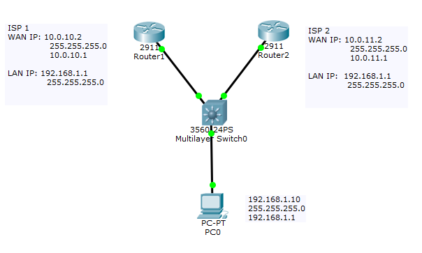
1. Configure the first router for your first ISP.
Router#conf t
Enter configuration commands, one per line. End with CNTL/Z.
Router(config)#ip route 0.0.0.0 0.0.0.0 10.0.10.1
Router(config)#exit
Router#conf t
Enter configuration commands, one per line. End with CNTL/Z.
Router(config)#int fastEthernet 2/0
Router(config-if)#description WAN
Router(config-if)#ip address 10.0.10.2 255.255.255.0
Router(config-if)#ip nat outside
Router(config-if)#no shutdown
Router(config-if)#exit
Router(config)#exit
Router#copy run start
Destination filename [startup-config]?
Building configuration...
[OK]
Router(config)#int fa2/1
Router(config-if)#description LAN
Router(config-if)#no shutdown
Router(config-if)#ip address 192.168.1.1 255.255.0.0
Router(config-if)#ip nat inside
Router(config-if)#standby 1 ip 192.168.1.3
Router(config-if)#standby 1 priority 105
Router(config-if)#standby 1 preempt
Router(config-if)#exit
Router(config)#exit
Router#conf t
Enter configuration commands, one per line. End with CNTL/Z.
Router(config)#ip name-server 8.8.8.8
Router(config)#ip name-server 8.8.4.4
Router(config)#exit
Router#copy run start
Destination filename [startup-config]?
Building configuration...
[OK]
Router(config)#ip access-list standard LAN
Router(config-std-nacl)#permit 192.168.0.0 0.0.255.255
Router(config-std-nacl)#exit
Router(config)#ip nat inside source list LAN int fa2/0 overload
Router(config)#exit
Router#copy run start
2. Configure the second router for your second ISP.
Router#conf t
Enter configuration commands, one per line. End with CNTL/Z.
Router(config)#ip route 0.0.0.0 0.0.0.0 10.0.11.1
Router(config)#exit
Router#conf t
Enter configuration commands, one per line. End with CNTL/Z.
Router(config)#int fa
Router(config)#int fastEthernet 2/0
Router(config-if)#description WAN
Router(config-if)#ip address 10.0.11.2 255.255.255.0
Router(config-if)#ip nat outside
Router(config-if)#no shutdown
Router(config-if)#exit
Router(config)#exit
Router#copy run start
Destination filename [startup-config]?
Building configuration...
[OK]
Router(config)#int fa2/1
Router(config-if)#description LAN
Router(config-if)#no shutdown
Router(config-if)#ip address 192.168.1.1 255.255.0.0
Router(config-if)#ip nat inside
Router(config-if)#standby 1 ip 192.168.1.3
Router(config-if)#standby 1 preempt
Router(config-if)#exit
Router(config)#exit
Router#conf t
Enter configuration commands, one per line. End with CNTL/Z.
Router(config)#ip name-server 8.8.8.8
Router(config)#ip name-server 8.8.4.4
Router(config)#exit
Router#copy run start
Destination filename [startup-config]?
Building configuration...
[OK]
Router(config)#ip access-list standard LAN
Router(config-std-nacl)#permit 192.168.0.0 0.0.255.255
Router(config-std-nacl)#exit
Router(config)#ip nat inside source list LAN int fa2/0 overload
Router(config)#exit
Router#copy run start
3. Configure the IP address of the client pc.
IP address: 192.168.1.10
Subnet Mask: 255.255.0.0
Gateway: 192.168.1.3
DNS Server: 8.8.8.8
4. Connect the 2 network cables from your 2 routers into the switch.
Try to type ping 8.8.8.8 on the command prompt on the computer that was
connected to the switch. Then unplug the cable of your first router from the
switch. The computer will be disconnected to the internet for few seconds. It will automatically connect to your second ISP.
Subscribe to:
Comments (Atom)


